Dual Channel Deflector
Dual Channel Deflector
|
Introduction and Use
|
Link to SPECIFICATIONS |
The pulser consists of two independent bipolar HV switches together with low level triggering control circuitry. The switches each will switch a capacitive load between 0 and 950V in response to a TTL input trigger signal. The pulser is to be connected to the load (typically a deflection plate in a ion optical system) via 100Ω cable (<1.2m) in length. Suitable leads are supplied with SHV connectors at the pulser end. Note that the load end is unprepared and the user must take care that adequate screening and insulation is provided at the load end to avoid a shock hazard.
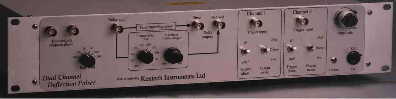
The low level circuitry includes a rate generator, a delay generator, phase switching (0 or 180°) and mode switching (high, triggered or low output). The various sections are connected via the front panel BNC connectors. The HV output is provided on the rear panel.
One of the rate outputs is used to drive the delay input, the other is available for external use, such as scope triggering. Note that the phases are different. The two outputs from the delay generator (delayed and direct) are used to drive each of the two pulser trigger inputs (channels 1 and 2). The direct output is a zero time reference and the relative delay of the delayed output is adjusted with the coarse and fine delay controls. The fine control gives a little more than 50ns adjustment to allow for continuous delay adjustment between the coarse (50ns) steps. The trigger phase controls allow the phase of each HV output to be inverted with respect to the trigger input. The mode controls allow each output to be forced low or high or to be slaved to the trigger input.
Normally the HV output is DC coupled however there is provision for the user to apply a DC bias to the switched output voltage. The use of an external bias will require the moving of internal links*. As shipped the BNC bias inputs on the rear panel are disconnected and the HV output is DC coupled.
The pulser is fan cooled and air flow must be allowed around the rear and base of the unit.