|
Self Matched Line & Reverse Terminated Lines |
||
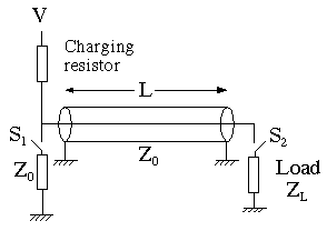
Consider the following circuit.

If both switches are closed simultaneously then any reflections
from the load are absorbed by the terminating resistor at the
left. The result is a square pulse into any resistive load with
an amplitude that depends upon the load resistance. If the load
is reactive there still will not be any reflections after two
round trip times of the cable although there may still be some
exponential components.
By activating the switches at different times it is possible
to vary the pulse length. It is necessary however, that the switch
S1 be closed by the time the edge from S2
arrives at S1 This configuration is used in our Photocathode pulser.
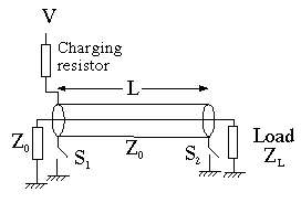
By rearranging the switches we can obtain

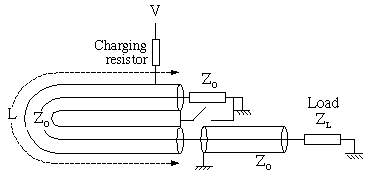
and then combining the switches into one and moving the grounding point:

This configuration although simple in principal does have the drawback that in co-axial geometry the outer of the cable has to be floated by the charge voltage. Also the two ends of the cable and the terminating resistor have to be in a very low inductance configuration to obtain a good risetime. The switch has to discharge not only the cable capacitance but also the stray cpacitance of the cable outer to ground. However, it can produce very good results if built carefully.

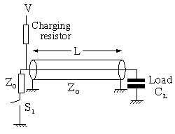
This configuration is useful for charging (or discharging) a capacitive load and is used in our simple "Q" switch pusler. The switch sends a step wave down the line of half the amplitude of the charge voltage. This arrives at the capacitive load which , after several RC=Z0 times will reflect the pulse delivering twice the step voltage into the capacitor. When this step arrives back at the switch it is absorbed in the terminating resistor. The result is that the voltage on the load stays there a long time.