|
Ramp balancers |
|||

|
Ramp balancers |
|||

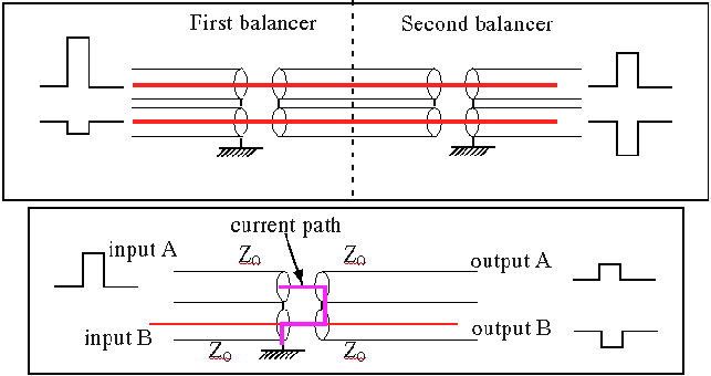
Consider a single pulse incident at input A. When it arrives at the balancer the input cable appears terminated by three cables of impedance Z0 in series. The transmission coefficient is
T= 2ZT/(Z0 + ZT)
ZT = 3Z0
![]() T = 1.5
T = 1.5
This is equally divided among the three arms, with 0.5 in each arm, but from the direction of the current flow in the diagram it can be seen that the component in output B is negative whilst that in output A and input B is positive.
In addition there is a reflection at the balancer, the reflection is given by
R= (ZT - Z0)/(ZT + Z0)
![]() R = 0.5
R = 0.5
So in summary for a positive input of unity amplitude into input A there is a component in each of the four arms with input A, input B and output A all positive and output B negative.
Similarly for a negative input of unity amplitude into input B there is a component in each of the four arms with input A, input B and output B all negative and output A positive.
Adding these we see that:
1 the reflections cancel
2 the outputs are equal and opposite
3 the output polarity of A equal that of input A and similarly for the Bs
Now consider that a difference occurs between the two inputs other than their polarity.
e.g. input A =1; input B = -1 +Δ
The signal from output A = 0.5 - 0.5(-1 + Δ) = 1 +Δ/2
The signal from output B = -0.5 (-1 +Δ) - 0.5 = -1(1 +Δ/2)
i.e. the signals are now balanced.
There is also a reflection into each input, but this is usually not important.
The balancing will not generally be as perfect as the theory might suggest as it has been assumed that all arms are equal. In practice stray capacitance and radiation will result in non perfect behavior. However, factors of ten improvement have been observed in balancing up unequal signals. By having a second balancer this is improved further.
Note also that the balancer shown only works on time scales less than the round trip time of the floating section. This could be increased by adding ferrite to stop common mode currents.