|
Impedance Matching and Mismatching
|
|
|
|
|
|
It is often necessary to drive resistive loads that have an impedance other than the typical 50Ω output impedance of a pulse source. The simplest solution is mismatch the load to the source. This results in reflections from the junction that go back to the pulse source and may be reflected by it, back to the load. Ideally one would build a wide bandwidth transformer at the junction. This can avoid the reflections and also transmit all the available energy to the load. If mismatches are necessary the user should be aware of the level of reflections fom the mismatch, the load and the source. Many loads, for example electron grids are insensitive to opposite polarity pulses and this may be used to obtain higher voltages at the load. Note that if two mismatches are used the efficiency of energy transfer can be higher than for a single mismatch; as all people working with coated optics already know. With two or more mismatches it is easily shown that the greatest efficiency is obtained when all the impedance ratios at each junction, are the same. This leads to the conclusion that, for a continuously changing impedance matching transformer, the impedance should change exponentially.
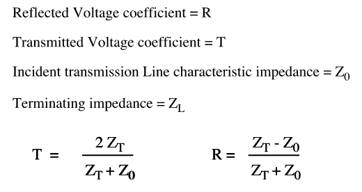
For a single mismatch the voltage reflection and transmission coefficients are given by:-

Note that although the current is related to the voltage by Ohm's law, one has also to allow for the reversal of direction of the pulse when considering current reflection coefficients.

