|
|
|
click for higher resolution picture
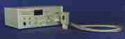
IntroductionThe High Rate Imager is a very high trigger rate gated intensifier intended for applications such as fluorescence lifetime imaging, lidar and time resolved spectroscopy. Its gate pulse driver has a bandwidth of 1GHz and it has internal pulse forming circuitry to provide gate widths to less than 500ps at trigger rates from single shot to greater than 100MHz. It features an internal microcontroller with a front panel LCD display and keypad for all functions (except analogue input attenuation level). In addition it has an RS232 interface to allow remote operation. It is able to provide RF modulation of the intensifier gain at frequencies up to 1GHHz.
The intensifier is provided in a remote housing with a flexible connection to the power supply. The input and output faces have mounting holes for the user to attach various optical accessories.
The output format is a flat fibre optic faceplate. We are able to provide CCD readout options or users may provide their own readout arrangements.
We are able to provide certain standard lens mounts at the input face as an option.
The power supply is self contained and includes trigger input conditioning circuitry, intensifier high voltage supplies and protection, gain control, bias circuitry and remote computer control.
Features
|
Intensifier
|
Operating modes
|
Controls
|
|
Indicators
|
Connectors
|
Description of gate modes
Slave (high duty cycle)
Gating specificationSlave mode
Comb mode
RF mode
Notes
This intensifier system is optimised for high speed gating for which the cathode drive impedance must be very low. The maximum gate voltage is therefore set by average power limitations. For the high duty duty cycle modes (slave mode at high duty cycle and RF mode) the drive voltage is reduced (nominal 24V p-p). For this reason the user should be aware that for low frequencies (<100MHz) the cathode modulation voltage is lower than may be obtained from a system designed specifically for lower frequency operation although it should be mentioned that the wide bandwidth of the HRI allows the gate voltage waveform to be non-sinusoidal providing faster on/off and off/on transitions than sinusoidal drive would allow. Normally the gate signal will be a square wave with sub-nanosecond rise and fall times. This may be expected to provide enhanced time resolution, even for lower drive frequencies.
If you wish to use only RF modulation but do not need the 1GHz bandwidth we are able to offer alternatives. The higher cathode gate voltage available with restricted bandwidth will provide (slightly) higher gain and resolution.
The low duty cycle modes are able to provide a higher switched voltage (50V p-p) as the dissipated power is reduced for the lower duty cycle.
We manufacture a 1MHz, 0.5ns imager. The lower repetition rate allows the application of a higher gate voltage at the cathode providing improved resolution and gate speed. If very high repetition rates are not required then this instrument may be more suitable.
We are able to provide double MCP intensifier options although when operated at high duty cycle the effective backgound illumination (EBI) level for the photocathode must be considered.
Very narrow gate widths are obtained from the HRI by operating the intensifier close to cathode cut-off. The shortest gate widths (400ps and less) are sensitive to the incident wavelength, signal level and reverse bias. In comb mode, when operated at 100MHz, it may be expected to obtain gate widths below 300ps, although the cathode will be operating only a few volts from cut off. If your application demands gate speeds in the range 200ps and below our GOI imager, providing sub 100ps gating at 1kHz repetition rate, may be more suitable.